
Inverting The Hull
The Roll (Theory)
It was soon found that whilst the better facilities enabled a more secure and inherently warmer environment in which to work. It still left areas that were difficult to get at with any degree of comfort. It was clear that in order to work on the underside of the boat safely the former lifeboat would have to be inverted! Even with today's equipment turning the hull safely over was not going to be an easy task. The trust's biggest concern was the safety of those involved in the task as well as the safety of the lifeboat hull. It was accepted that turning the hull the boat would undergo stresses far in excess what one would have deemed possible on a lifeboat this old, even though the hull is in extremely good condition for its age, the safety of those involved was paramount. A plan was drawn up that would eventually make things far safer. The plan was to more or less encase the hull in two wooden sheeting templates encircling the hull placed forward and rear to the hulls centre beam. A number of scaffold tubing bars would then be fitted for and aft around the templates in an effort to make the whole outfit more rigid. To complete the assembly a set of strong rollers welded into a "H" beam would be placed underneath the hull to allow the whole set up to be managed safer.
On paper or in theory it sounds so easy to do, the reality however, is far harder to actually achieve! Considerable time was spent working on a suitable plan of how the design should look before a scaled down model of the hull and the assembly was made. The front of the trailer holding the lifeboat had a large section at the front that was substantially higher than the flatbed part. It was this element that created many problems, in order to overcome this problem a roller assembly was designed.
The Scaled Model
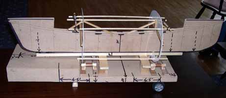
The photograph above gives some idea of how the assembly would look when built. The roller assembly beam can be seen running the length of the hull fore and aft at the height of the raised part of the trailer. The photograph clearly outlines where it was hoped the templates and scaffold tubing should be placed. The plans for the turning and the scaled model were put before a general meeting of trustees and people interested in our project and a lengthy discussion ensued, the plan was amended to represent valid points brought forward. Before embarking on any practical work the trust sought professional advice on the effectiveness and safety of turning the hull. The former lifeboat is of such importance to Whitby's heritage that it would not have embarked on the turning exercise if it was deemed irresponsible or unsafe. Having taken professional advice the consensus was that whilst a little complex the condition of the hull was deemed such that it was suitable for the manoeuvre and that it was thought within the capabilities of the working team!
The Roll (Practical)
Making and fitting the actual hardware was not going to be easy but thought within the trust capabilities. The steel scaffold tubing was pretty simple, as this would only entail cutting the necessary tubing to length prior to fitting it. The wooden templates were going to be made from sheeting that the trust was in effect recycling, however the roller assembly took the lion's share of work and the part that eventually created the greater frustration. The trust has to make the best use of what funding was available to them at the time and it was thought that using two sections of heavy duty angle iron readily available would make up for what costs would be incurred if a new section of "H" girder were purchased.
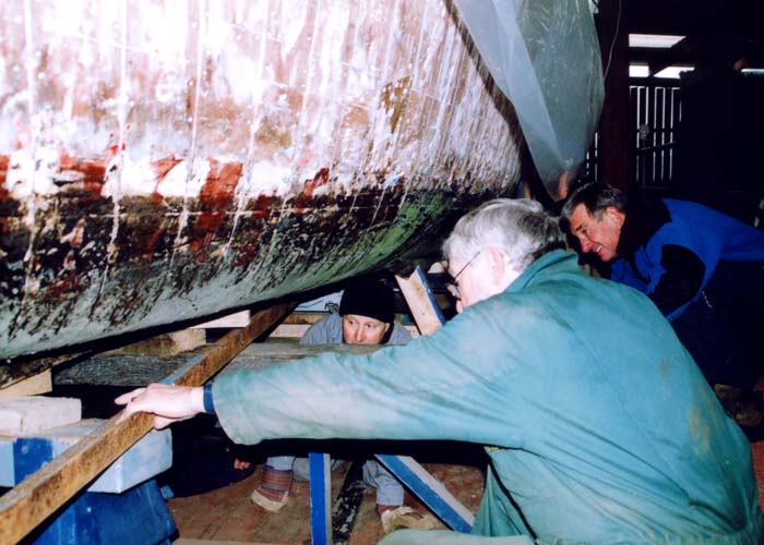
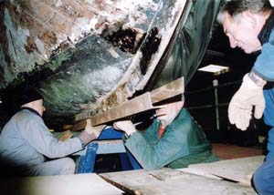
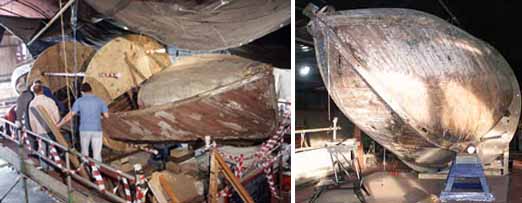
The trust was also trying to reclaim items for use during the restoration, not only as a costing cutting exercise but too reduce its carbon footprint. The photograph to the left gives a clear indication of the complexities of the working area and as usual Tim was in the thick it underneath the boat? There is not a lot of room between the hull and the trailer and Tim was always volunteering. The photograph (below) perfectly illustrates the two sections of angle iron being slotted under the hull. From this point the sections were extensively welded to ensure that there was no chance of them splitting under load. The idea was that when the hull was lowered onto the rollers it could be rolled into a position whereby the hull was supported equally on the trailer making it not only more stable but more importantly safer to carry out the roll manoeuvre.
Once the welding task was completed it was decided that before going ahead with making the templates that a trial run of 'rolling' the hull backwards and forwards be tried first, it was at this point that whole exercise hit its first step backwards. After the many hours put into making the roller assembly the hull refused to move along on the rollers, it obviously needed more thought and the working team had little choice but to go back to the drawing board.
It also became apparent at this point that the effective height of the lifeboat was such that unless the hull was taken off the trailer and lowered that it would not be possible to roll the hull through 180 degrees. The original plan was to completely invert the hull during one single revolution. It was believed that doing so this way would limit the stresses on having to turn the hull on different occasions. Unfortunately this was no longer really practical and the trust instead remained positive that turning the hull almost 90 degrees one way would give ample room to work on the hull, before repeating the exercise the opposite way to do the other side. It is not quite what was originally planned, but then the trust and its working teams were effectively on a learning curve and had to amend plans where necessary.
The Wooden Templates
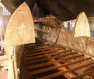
Surplus wooden sheeting had been acquired by the trust well in advance and separated to make sure each sheet was allowed to dry through. In July 2005 the trust was fortunate enough to have the services of a unit of army cadets who cut the templates from one previously made by the working party. The sheeting was later offered up to the hull and secured in place. The first two wooden sheets can be seen secured in place as well as the additional strengthening at the deck level which would help support the hull for the rolling exercise.
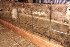
As well as the lateral hardwood slats placed to maintain the beam integrity a section of lighter coloured planking can be seen below these slats. This lighter coloured planking was actually a very substantial wooden beam secured along the length of the hull, which would potentially restrict the keel section from hogging or sagging when inverted.
In order to secure the beam it was necessary to utilise the original bolt holes used for fitting the actual keel and long lengths of threaded rod. The task of aligning the holes and drilling the new holes in the support somehow turned into quite a task, it was however, critical to make sure that each of the holes was aligned. The photograph to the left shows part of the wooden sheeting cut out to form the lower section of the wooden templates, the very part that would hold the weight of the boat on the rollers.
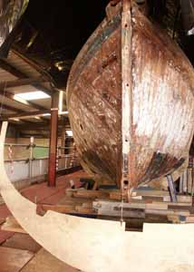
Finally with everything in place the trust called on willing hands to try out the assembly. The hull was tentatively lowered onto the roller assembly and whilst the hull was beginning to roll with pressure it was clear some small modifications were needed. It was not too long before the changes necessary were made and with help from those present the roll was achieved. In situ it was possible to turn the hull through 45 degrees and it was decided that this would be enough for the work to proceed on the underside. The photograph below is a good example of the hull rolled so that work can be carried out, in this position the hull looks quite precarious.
Copyright © Colin Brittain 1999 - 2022